Oscilloscope is typically used for counting the frequency or magnitude of the voltage (amplitude) of a wave or electrical signal. Most people will use an oscilloscope to observe the shape of a sinusoidal waveform of the circuit or power source of alternating current or AC (Alternating Current) so that counting can directly magnitude below the peak amplitude of the wave to the top of the top, so it is often known as the peak to peak voltage (Vpp). But to do the calculations and get an accurate result it must be ascertained in advance that we will use the oscilloscope has been calibrated or not. To determine if the oscilloscope has been calibrated or how to calibrate I will explain as follows.
Oscilloscope basically there are a few main buttons that have different basic functions, among others.
Volt / div is used to set the voltage measurement or amplitudo in 1 box or div to limit the position of the top and bottom of the box. More precisely to determine the magnitude of the voltage which is calculated in each box.
Time / div is used to determine the limit of the measurement period (in seconds) or limit the left side and right side in one box or div.
Mode is to determine which channel is active or appear in the display. Generally can be one channel or both channels simultaneously, even to combine both the channel.
var on the volt / div is used to calibrate the voltage on each channel on the oscilloscope. The effect on the settings button that changes the distance up and down on one wave.
var on time / div is used to calibrate the period on all channel oscilloscope. Securities that comes up on the settings button that changes the distance left and right on the first wave.
Position on y to adjust and shift the location of the top and bottom of the wave on the screen.
Position on x to adjust and shift the location of the left and right waves on the screen.
For more details please look at all the buttons on the oscilloscope picture below .
 |
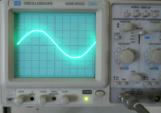
| Oscilloscope |
 |
| The main image on the oscilloscope. |
After all the functions of the buttons on the oscilloscope are understood then we can begin to do the calibration. First, we turn first osiloskopnya. Ensure that there is a line drawing on the screen and it was clear and not blurry. Where do they blur the focus setting prior to turning the focus knob below the screen, and check whether the line that looks slanted or straight? If a line appears slightly tilted immediately fixed by turning the settings on the slope of the hole in the bottom of the screen by using a screwdriver (-) small. After all the initial setup has been completed, immediately prepare an oscilloscope probe to be used. Since the function of the oscilloscope probe is very important to connect each channel oscilloscope on the device which we will measure and can be used to calibrate the oscilloscope itself. Oscilloscope probe itself is in addition to functioning as a link can also be used as a factor when the sources nor will we measure the circuit has a voltage oscilloscope than the maximum capacity, because there is a switch on the oscilloscope probes were labeled X1 and X10. The switch is usually only found on the original oscilloscope probe so by putting the X10 position we can still measure the voltage source greater than the measuring oscilloscope (volts / div) to 10-fold the maximum limits of the oscilloscope. But for homemade oscilloscope probe we can only use a maximum limit 1X on the oscilloscope.
 |
| Picture Probe oscilloscopes |
 |
| Determining the mode on channel 1 |
 |
| Placing the oscilloscope probe to the terminal cal. |
 |
| Waveforms are in calibration voltage. |
 |
| Setting time / div for frequency calibration |
 |
| Waveform after calibration voltage and frequency |
 |
| Testing oscilloscope with an AC voltage source |
 |
| Waveform sine amplitude limit |
 |
| Waveform after setting the limit amplitude (volts / div). |
 |
| Waveform after adjustment period (time / div) |
 |
| Adjustment of the position to calculate the period of a wave |
For counting frequency then we need to know in advance the wave period. Based on the picture above it appears that the period (end nodes left and right) are 10 div x 2 ms / div = 20 ms. So the frequency is 1 / T = 1/20 ms = 1/0, 02 s = 50 Hz. Means of measurements using an oscilloscope on the output transformer 12 volts is 12.019 volts AC with a frequency of 50 Hz.
Hopefully above is useful as a baseline early, especially those wanting to learn more about Lissajous oscilloscope to find a model, compute the op-amp gain, integrator and differentiator.
Keep in mind that some models of the oscilloscope to the location of the button may vary slightly, but all the functions are the same as described above.
No comments:
Post a Comment